
I. Overview
This guide will walk you through a basic LED blinking example on the STM32F411 microcontroller, based on the openvela real-time operating system. You will learn the basic workflow of using openvela, including setting up the development environment, compiling the project, flashing the firmware, and registering and using the LED driver.
II. Final Result
III. Preparations
1. Hardware
- Development Board: A board based on the STM32F411.
- Debugger: An ST-Link V2 debugger (or the onboard ST-Link).
- Serial Tool: A USB to TTL serial module for viewing log output.
- Cables: A USB data cable and several Dupont wires.
2. Software and Toolchain
Please install and configure the following software on your development host (Ubuntu).
-
Set up the openvela development environment.
Please refer to the official Quick Start document to set up the basic openvela development environment.
-
Install the ARM GCC toolchain.
This toolchain is used to compile firmware for the target platform. Open a terminal and execute the following command:
sudo apt install gcc-arm-none-eabi binutils-arm-none-eabi -
Install STM32CubeProgrammer.
This tool is used to flash the compiled firmware to the STM32 microcontroller.
-
Download Link: Please download the version matching your operating system from the ST official website and complete the installation.
-
Install Dependencies: To ensure STM32CubeProgrammer can correctly identify USB devices, please install libusb.
sudo apt-get install libusb-1.0.0-dev
-
-
Install ST-Link drivers.
To allow the Linux system to access the ST-Link device with normal user permissions, you need to install udev rules.
-
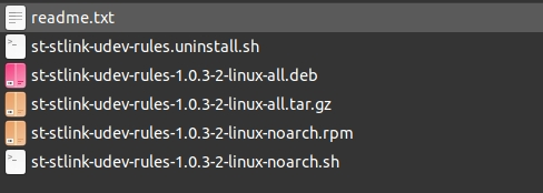
Download Link: Please download the stsw-link007 package from the ST official website and extract it.
-
Run the installation script: Follow the instructions in the readme.txt file within the package to install the udev rules.
sudo sh st-stlink-udev-rules-*-linux-noarch.sh
-
-
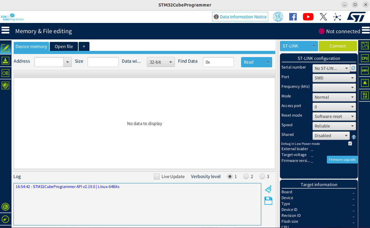
The startup interface looks like this:
3. Hardware Connection and Verification
-
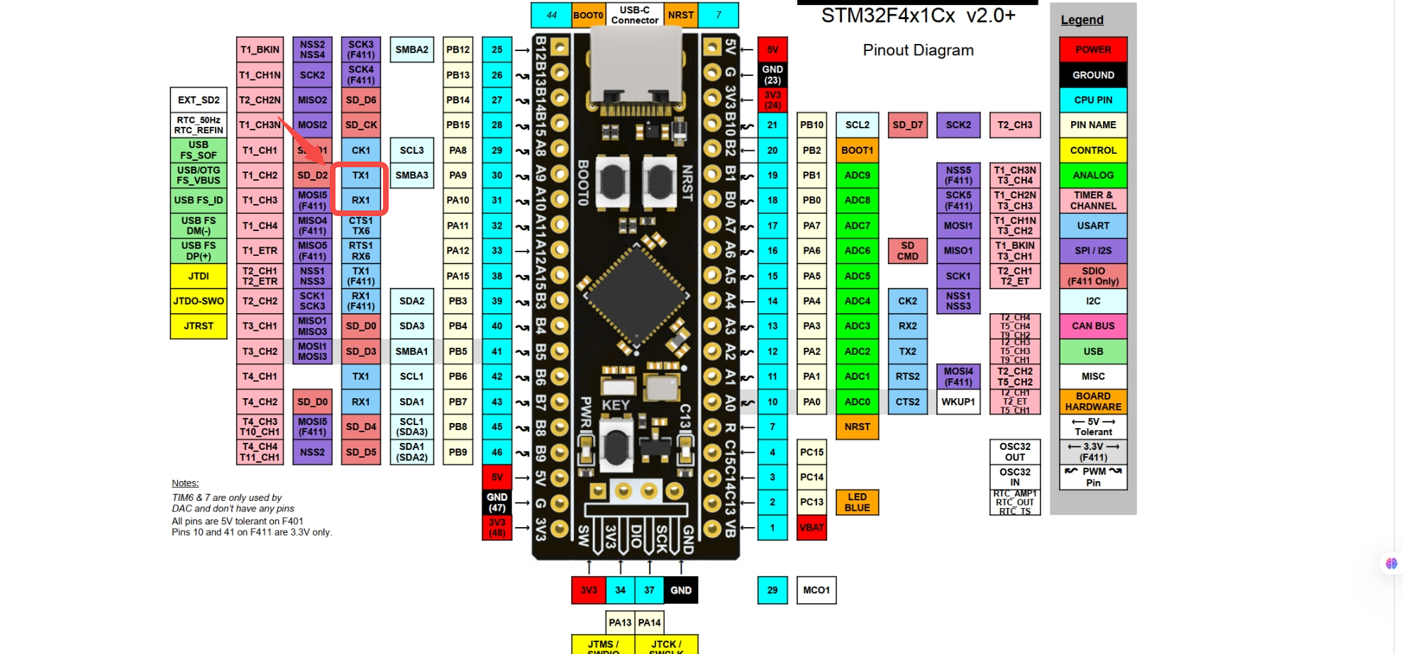
Refer to the schematic to prepare the hardware connections.
-
Please connect the components as shown in the table below.
From To Description PC USB Port ST-Link Debugger USB Port Power and Debugging USB to TTL Module TX Board PA10 (USART1_RX) Serial Communication USB to TTL Module RX Board PA9 (USART1_TX) Serial Communication USB to TTL Module GND Board GND Common Ground A reference for the physical connection is shown below:
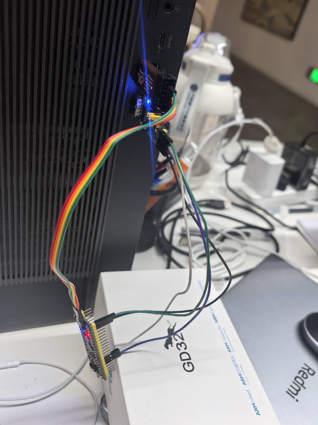
-
Verify the connection.
Use the STM32CubeProgrammer tool to verify if the hardware connection is successful.
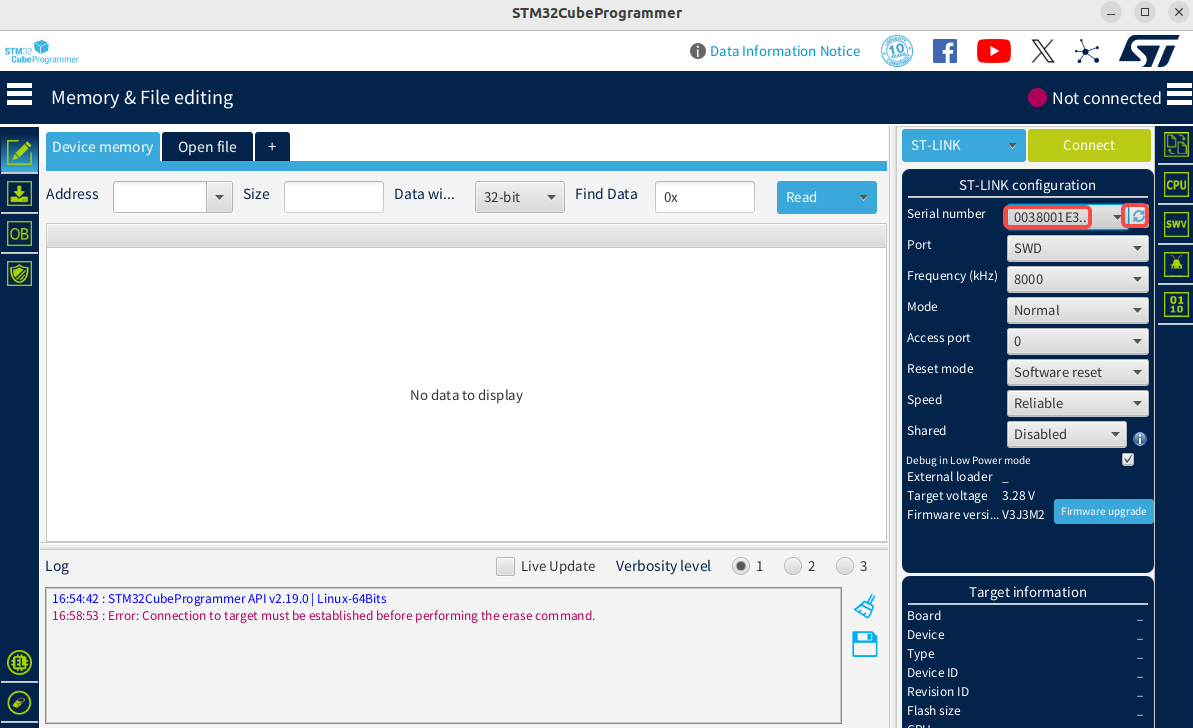
- Launch STM32CubeProgrammer.
-
In the ST-LINK Configuration area in the upper right, click the Refresh button. If a device serial number appears in the Serial number dropdown list, the debugger has been successfully recognized.
-
Select Erasing & Programming from the left navigation bar, as shown below:
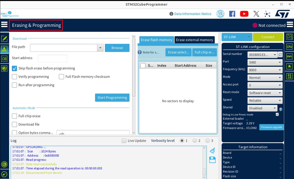
-
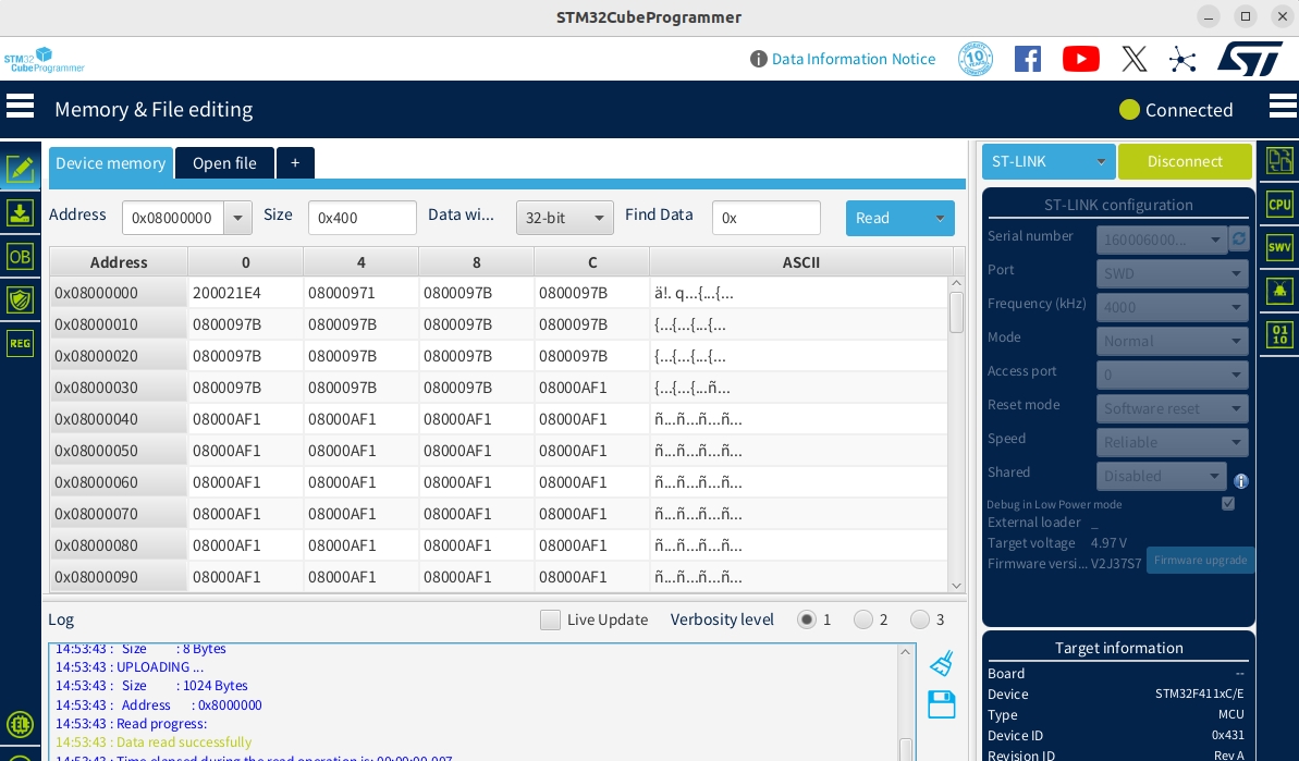
Select the J-Link or STLINK method and click the green Connect button. When the button changes to Disconnect, it means the development board is successfully connected, as shown below:
IV. Running the Demo
This section will guide you on how to compile and run an LED blinking example for the STM32F411-minimum board based on the openvela source code.
1. Get the Sample Code
Please ensure you have the complete openvela source code ready locally, following the official documentation Download openvela Source Code.
2. (Optional) Understand the Project Structure
The openvela code follows a layered design. Understanding the key directories will help with future custom development.
- Application Layer (Examples): nuttx-apps/examples/leds
- Board Support Package (BSP): nuttx/boards/arm/stm32/stm32f411-minimum
The table below briefly describes the function of core directories:
| Directory Path | Function Description |
|---|---|
| nuttx/boards/arm/stm32/stm32f411-minimum/src | Contains STM32F411 board-specific driver implementations, such as GPIO initialization and device registration (e.g., /dev/userleds). |
| nuttx/arch/arm/src/stm32 | Contains generic SoC-level drivers for the STM32 chip family, such as low-level R/W and clock configuration for I2C, SPI, GPIO. |
| nuttx/drivers | Contains upper-layer driver interfaces compliant with the openvela standard driver model. Applications interact with hardware through these standard interfaces. |
3. Load and Configure the Project
-
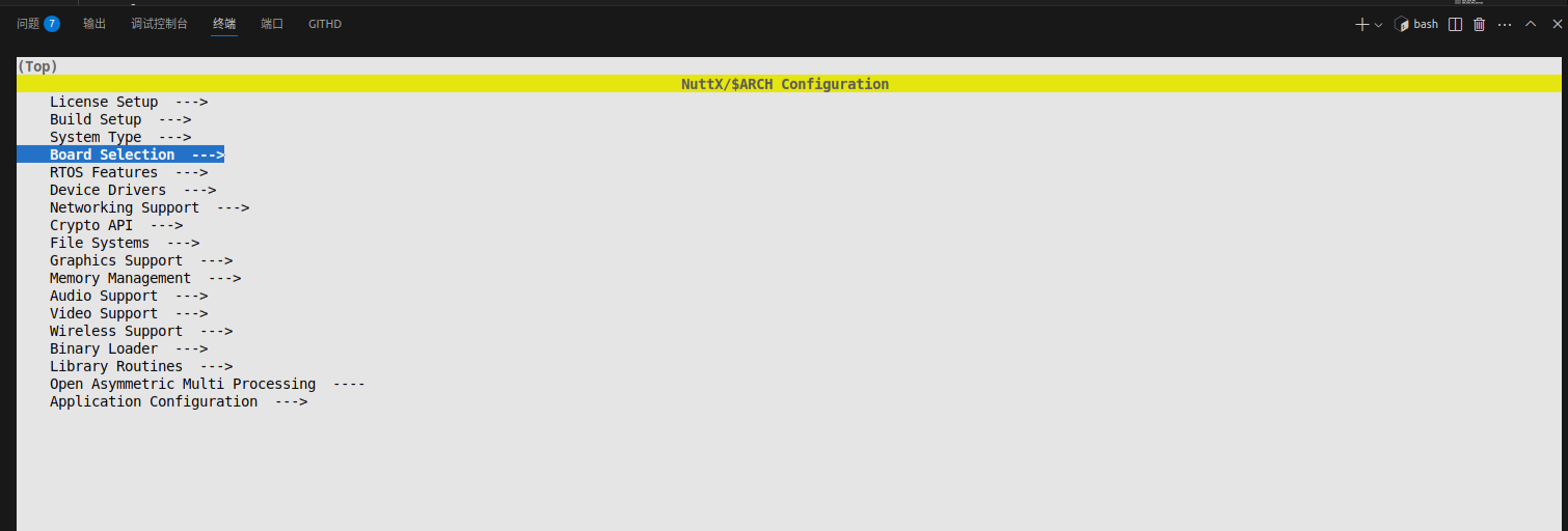
Execute the following command to open the menuconfig configuration interface:
./build.sh nuttx/boards/arm/stm32/stm32f411-minimum/configs/rgbled menuconfig -
Select the target board.
-
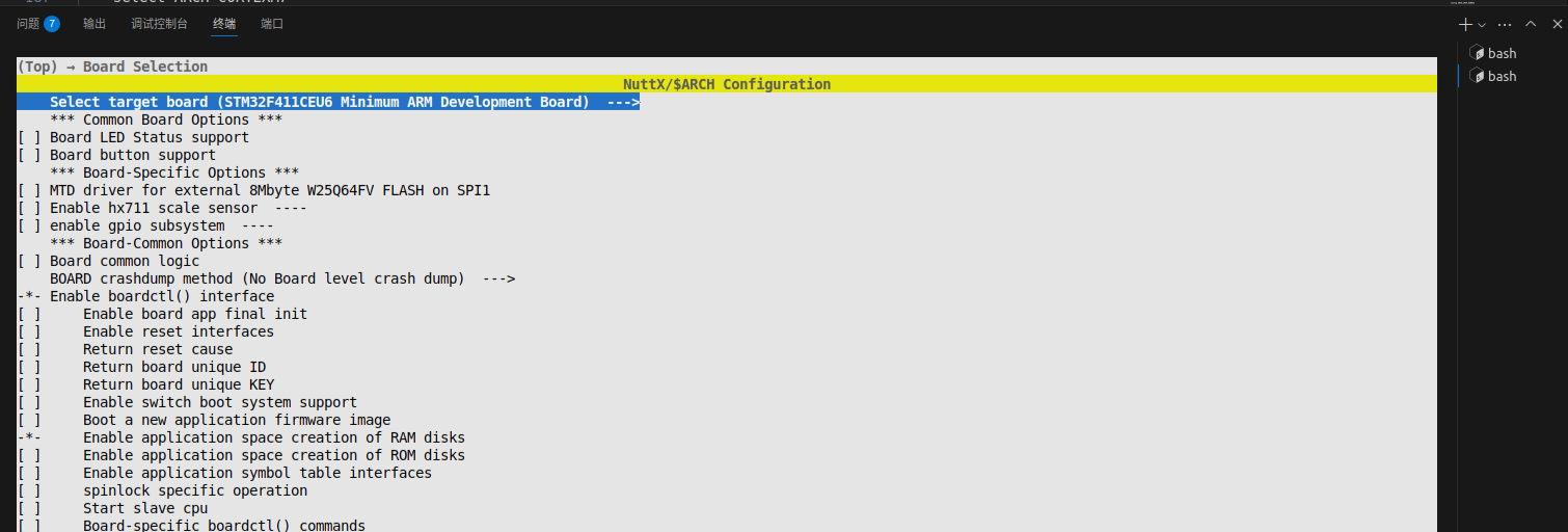
Press Enter to go to Board Selection and open the board selection menu.
-
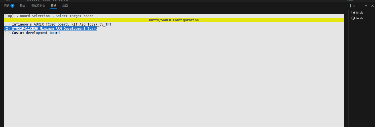
Press Enter to select Select target board and choose the target platform to compile for:
-
ress Enter to select STM32F411CEU6 Minimum ARM Development Board to compile firmware for the STM32F411CEU6 minimum system board:
-
-
Enable the LED driver.
-
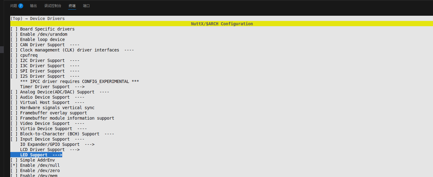
Press Esc twice to return to the top-level menu, then select Device Drivers:
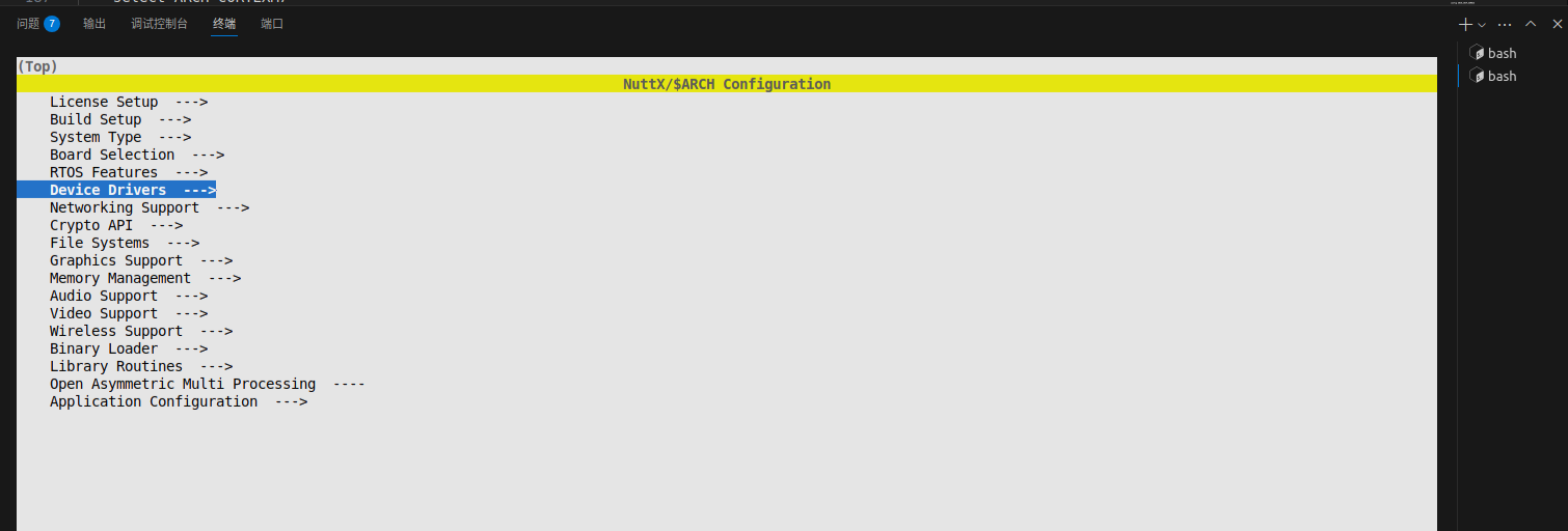
-
Press Enter to go into LED support:
-
Enable the following configuration options:
- LED driver
-
Generic Lower Half LED Driver
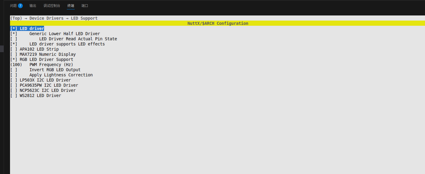
-
-
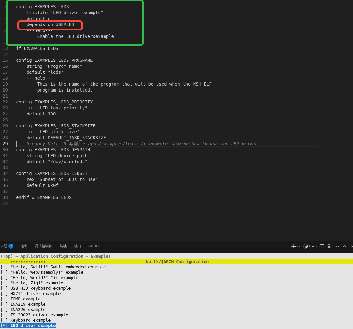
Enable the example program.
-
Press / to search for and enable EXAMPLES_LEDS.
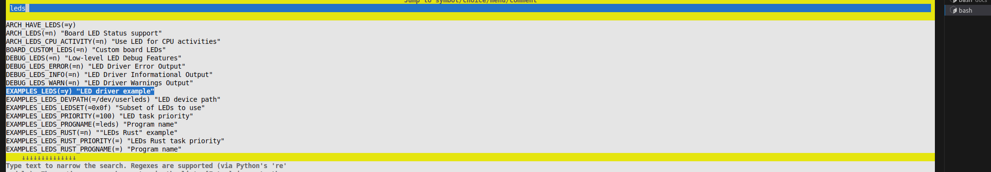
-
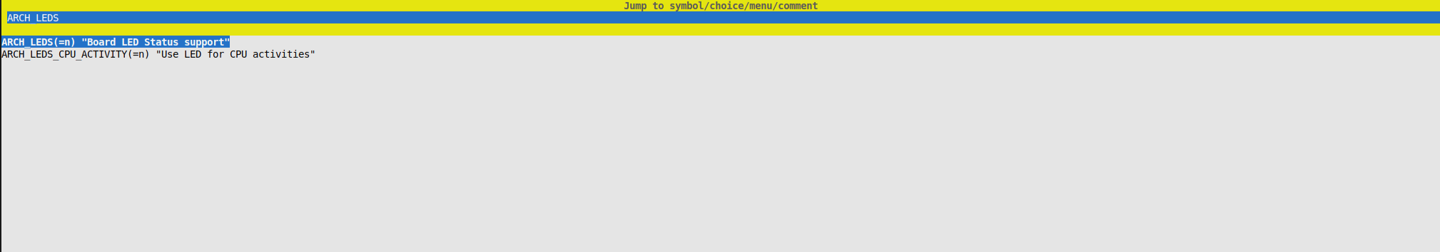
Press / to search for and disable ARCH_LEDS (to avoid conflicts).
-
-
Save the configuration. Press Q to exit the menu and select Y to save the configuration.
4. Compile the Project
-
Return to the openvela root directory and use the following command to compile the LED example program:
./build.sh nuttx/boards/arm/stm32/stm32f411-minimum/configs/rgbled -j8 -
After a successful compilation, nuttx.hex and nuttx.bin firmware files will be generated in the nuttx directory.
5. Flash the Firmware
- Launch the STM32CubeProgrammer tool and connect to the development board.
-
Click Browse, select the firmware file generated in the previous step, openvela/nuttx/nuttx.hex, and check the box for Skip flash erase before programming, as shown below:
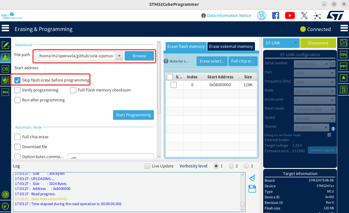
-
Click Start Programming to begin downloading. A pop-up will appear upon completion, and the log window will display relevant information.
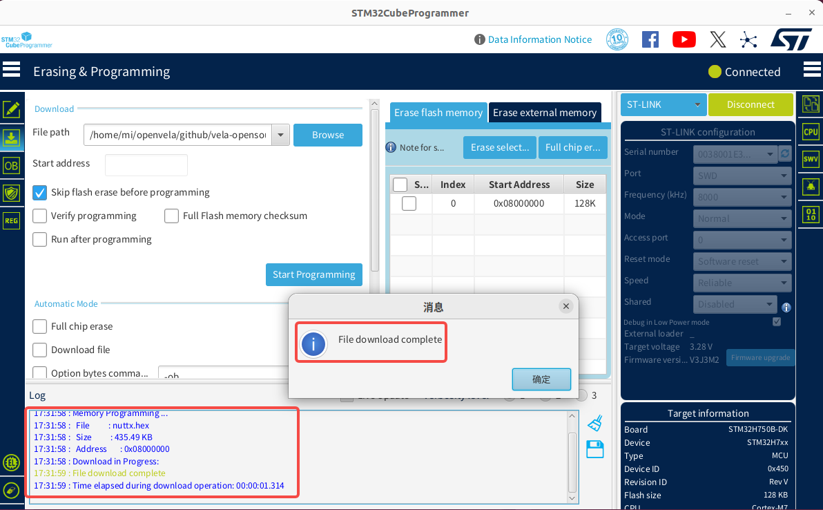
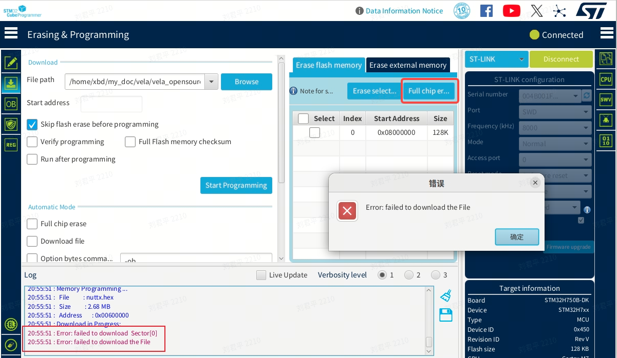
-
If an Error occurs during the download, click the Full chip erase button to erase the chip data, then try downloading the firmware again.
6. Connect to the Serial Port
-
Use Minicom or another serial terminal tool to connect to the board.
# Note: Your device might be ttyACM1, please modify accordingly. sudo minicom -D /dev/ttyACM0 -b 115200 -
(Optional) If Minicom does not accept keyboard input on the first use, follow these steps to modify its configuration:
-
Use the following command to open the Minicom configuration interface:
sudo minicom -s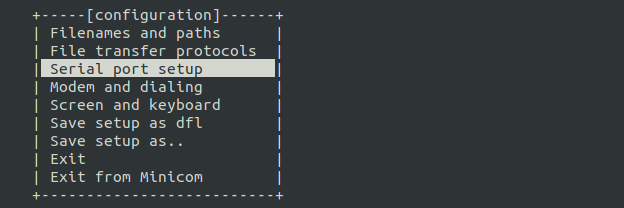
-
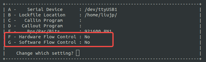
Go to the Serial port setup menu and ensure the following two options are set to No:
- Hardware Flow Control: No
-
Software Flow Control: No
-
Select Save setup as dfl to save as the default configuration, then Exit.
-
Reconnect. If problems persist, press the Reset button on the development board.
-
7. Run the LED Example
-
Reopen Minicom. After a successful connection, press Enter in the terminal, and you will see the nsh> prompt.
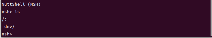
-
To run the LED example, enter the following command:
leds -
You will see the user LED on the board start blinking, and the serial terminal will output run logs.
V. How to Add a New Demo
This chapter will guide you on how to add, configure, and run a custom LED control application in the openvela packages/demos directory.
1. Core Steps Overview
Integrating a new application into openvela primarily follows this workflow:
- Create Application Files: Create a new directory under packages/demos/ and write the application's C source code, Kconfig, and Makefile.
- Register the Application with the Build System: Modify the parent Make.defs file so the build system can discover your new application.
- Configure and Compile: Enable the new application via menuconfig and compile to generate firmware with the new feature.
- Run and Verify: Flash the firmware and run your demo via a terminal command.
2. Create Demo Source Code and Configuration Files
-
Create the led directory:
# Ensure you are in the openvela source root directory mkdir -p packages/demos/led -
Create the C source file (packages/demos/led/led_main.c): This file contains the core logic of the demo, interacting with the low-level LED driver via the ioctl system call.
/**************************************************************************** * Included Files ****************************************************************************/ #include <nuttx/config.h> #include <nuttx/leds/userled.h> #include <sys/ioctl.h> #include <stdio.h> #include <stdlib.h> #include <fcntl.h> #include <unistd.h> /**************************************************************************** * Public Functions ****************************************************************************/ int main(int argc, char *argv[]) { int fd; int ret; userled_set_t ledset; // Define a set of LED states printf("Starting LED Demo...\n"); // 1. Open the userled device driver fd = open("/dev/userleds", O_WRONLY); if (fd < 0) { printf("Failed to open /dev/userleds, please ensure USERLED is enabled.\n"); return -1; } // 2. Turn on the first LED (usually LED 0) printf("Turning ON LED 0.\n"); ledset = 1 << 0; // Use a bitmask to select the first LED ret = ioctl(fd, ULEDIOC_SETALL, (unsigned long)ledset); if (ret < 0) { printf("ioctl(ULEDIOC_SETALL) failed: %d\n", ret); close(fd); return -1; } sleep(2); // Stay on for 2 seconds // 3. Turn off all LEDs printf("Turning OFF all LEDs.\n"); ledset = 0; ioctl(fd, ULEDIOC_SETALL, (unsigned long)ledset); // 4. Close the device close(fd); printf("LED Demo finished.\n"); return 0; } -
Create the Kconfig file: This file creates a separate configuration option in menuconfig to control whether this demo is compiled.
packages/demos/led/Kconfig:
# Defines the configuration option for the custom LED Demo. # This will appear under "Application Configuration -> Demos". config APP_DEMOS_LED bool "Custom LED control demo" default n depends on USERLED # This demo requires the base USERLED driver ---help--- Enable this to build the custom LED control demo, which demonstrates how to turn an LED on and off via ioctl.Note: We created a separate APP_DEMOS_LED option instead of reusing EXAMPLES_LEDS. This makes the new demo's logic clear and its configuration simple, avoiding unnecessary dependencies and confusion.
-
Create the Makefile: This file defines the compilation rules for this application, such as the program name, priority, and stack size.
packages/demos/led/Makefile:
include $(APPDIR)/Make.defs
# Application details, linked to the Kconfig option
PROGNAME  = led_demo
PRIORITY  = 100
STACKSIZE = 2048
# Source file for the application
MAINSRC = led_main.c
include $(APPDIR)/Application.mk
3. Register the New Demo with the Build System
Edit the Make.defs file in the packages/demos/ directory to add our led demo to the compilation list.
-
Open the packages/demos/Make.defs file.
-
Add the following code at the end of the file:
# ... (other demo configurations might be here) ...
# Add our custom LED demo to the build if it's enabled in Kconfig.
ifneq ($(CONFIG_APP_DEMOS_LED),)
CONFIGURED_APPS += $(APPDIR)/packages/demos/led
endif
4. Configure and Compile
Configure the Project
Return to the openvela root directory and run menuconfig.
./build.sh nuttx/boards/arm/stm32/stm32f411-minimum/configs/rgbled menuconfigEnable Required Configurations
In the menuconfig interface, ensure the following two options are enabled (you can use / to search):
-
Enable the low-level LED driver (dependency)
- Path: Device Drivers ---> LED Driver Support ---> [*] User LED Support
- Ensure CONFIG_USERLED is checked.
-
Enable the LED Demo
- Path: Application Configuration ---> Demos ---> [*] Custom LED control demo
- Ensure CONFIG_APP_DEMOS_LED is checked.
Save the configuration and exit.
Compile the Project
Switch to the openvela root directory, clean the previous build, and then build the project:
# (Optional but recommended) Clean previous build artifacts
./build.sh nuttx/boards/arm/stm32/stm32f411-minimum/configs/rgbled distclean
# Build the project with the new configuration
./build.sh nuttx/boards/arm/stm32/stm32f411-minimum/configs/rgbled -j8
5. Run the Demo
Please follow the instructions in Chapter 4 to run the demo.
-
Flash the firmware: Follow the instructions in Flash the Firmware to flash the newly generated nuttx/nuttx.hex file.
-
Run the command: Connect to the serial terminal and, at the nsh> prompt, enter the program name defined in the Makefile, led_demo.
nsh> led_demo -
Observe the results:
- You will see log output like Starting LED Demo... in the terminal.
- Simultaneously, the user LED on the board will turn on for 2 seconds, and then turn off.
VI. FAQ
1. undefined reference to board_userled... error during compilation
Symptom
After configuring menuconfig and running the build, a linker error similar to the following undefined reference occurs.
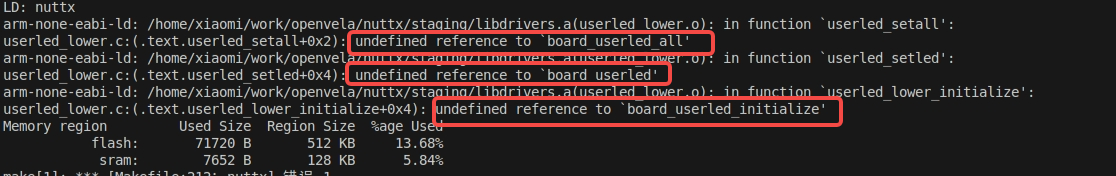
Cause Analysis
This is a configuration conflict between the generic USERLED driver and the board-specific ARCH_LEDS driver.
- CONFIG_USERLED=y: Enables the generic /dev/userleds driver framework. This framework relies on low-level board_userled... functions to perform actual hardware operations.
- CONFIG_ARCH_LEDS=y: Enables the board-level LED driver. In this mode, the system assumes that LEDs are controlled directly by architecture-specific code, so it does not compile and link the board_userled... related functions. This causes the USERLED driver to fail to find its implementation, resulting in a linker error.
Solution
Disable the board-level ARCH_LEDS driver to allow the generic USERLED driver to work correctly.
-
Enter menuconfig:
./build.sh nuttx/boards/arm/stm32/stm32f411-minimum/configs/rgbled menuconfig -
Disable ARCH_LEDS.
-
Clean and recompile:
# Clean old configuration and build artifacts
./build.sh nuttx/boards/arm/stm32/stm32f411-minimum/configs/rgbled distclean
# Recompile the project
./build.sh nuttx/boards/arm/stm32/stm32f411-minimum/configs/rgbled -j8
2. Program reports Failed to open /dev/userleds at runtime
Symptom
When running the demo in the terminal, the program outputs an error message and cannot open the device file.

Cause Analysis
This issue indicates that the /dev/userleds device node has not been created. This is usually because openvela's generic USERLED driver was not enabled in the configuration, so the relevant code was not compiled into the firmware.
Solution
As described in the demo's Kconfig file, enable the EXAMPLES_LEDS and USERLED configurations.
3. What is the difference between the packages/demos and nuttx/apps/examples directories?
-
https://github.com/open-vela/nuttx-apps/tree/dev/examples
- Source: Official NuttX community.
- Content: Contains various examples maintained by the NuttX community to demonstrate its core features.
- Nature: Generic, application-agnostic.
-
https://github.com/open-vela/packages_demos
- Source: openvela project.
- Content: Contains examples created to showcase specific openvelaela features or integration solutions.
- Nature: Customized for openvelapenVela, tightly coupled with the project.
-
Development Recommendation: When adding custom demos or applications to your openvela project, it is highly recommended to create them in the packages/demos directory.
VII. References
-
Deploying openvela on STM32H750
- A concrete, end-to-end hardware deployment case study.
-
- The definitive guide to understanding the underlying mechanisms of NuttX. The Build System and Kconfig sections are especially crucial for adding new components.
-
STM32CubeProgrammer Software Guide
- Learn how to use the official ST tools for operations like flashing firmware and configuring option bytes.