
I. Overview
This guide instructs you on how to compile, build, and run the openvela operating system in protect mode on the Flagchip FC7300F8M-EVB development board.
The FC7300F8M-EVB is a high-performance reference board based on the FC7300F8MDT chip, suitable for scenarios such as domain controllers and Battery Management Systems (BMS).
II. Expected Results
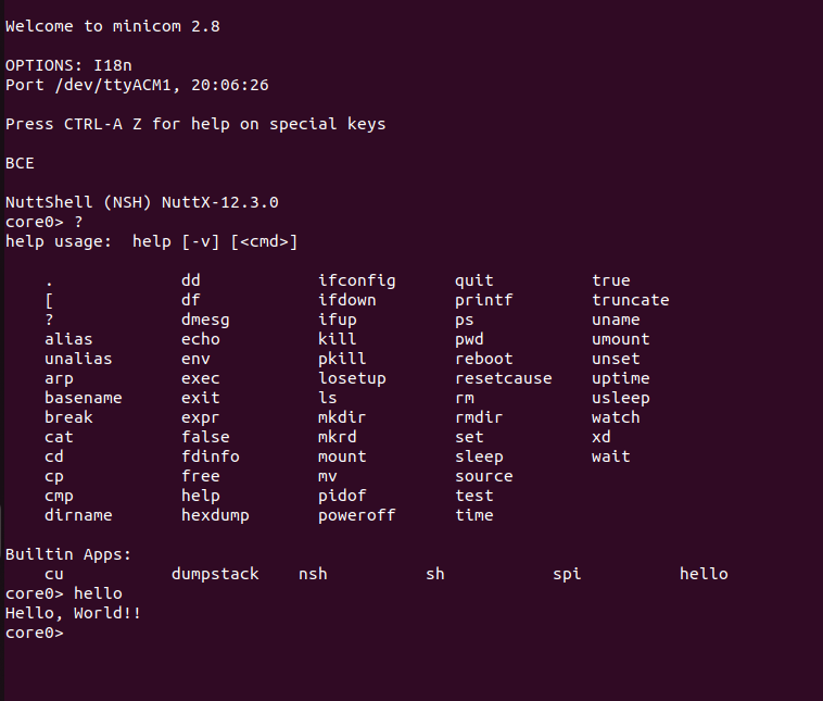
Upon completing the steps in this guide, you will successfully start the system and access the NSH (NuttShell) interactive terminal via the serial port (using the Minicom tool).
III. Prerequisites
Please ensure you have prepared the following hardware devices and completed the software configuration on your development host (Ubuntu environment).
1. Hardware Preparation
- Development Board: One FC7300F8M-EVB development board.
- Debugger: SEGGER J-Link debugger (supporting SWD mode).
- Cables: Power cable and USB data cable.
2. Basic Environment Setup
Please refer to the official document Quick Start (Ubuntu) to complete the environment setup and source code download.
3. Install J-Link Driver and Patch
To support FC7300 series chips, you need to install the J-Link driver and apply specific device patches.
Step 1: Install JLink Driver
Obtain the JLink_Linux_V688a_x86_64.deb installation package and execute the following command to install it:
Download JLink_Linux_V688a_x86_64.deb
sudo dpkg -i ./JLink_Linux_V688a_x86_64.debStep 2: Add FC7300 Device Support
Obtain the device patch package JLink_Patch_v2.19.7z and execute the following commands to apply the patch to the J-Link installation directory.
Note: Please replace <patch_path> with the actual path where you store the patch file.
# 1. Decompress the patch package
sudo apt update
sudo apt install p7zip-full
7z x JLink_Patch_v2.19.7z

# 2. Copy device definition files
sudo cp -rf <patch_path>/JLink_Patch_v2.19/Devices/* /opt/SEGGER/JLink/Devices/

# 3. Update the device configuration file (JLinkDevices.xml)

# Scenario A: If the /opt/SEGGER/JLink/JLinkDevices.xml file does not exist, execute the following copy command
sudo cp -rp /home/mi/XXX/JLink_Patch_v2.19/JLinkDevices.xml  /opt/SEGGER/JLink/JLinkDevices.xml

# Scenario B: If the configuration file already exists
# If the /opt/SEGGER/JLink/JLinkDevices.xml file already exists, please append the content within the <DataBase> tag from the JLinkDevices.xml file in the archive to the <DataBase> section of the /opt/SEGGER/JLink/JLinkDevices.xml file.
IV. System Build and Execution
This chapter details how to compile the Bootloader (BL) and Core0 system images and flash them to the development board.
1. Compile the Project
Enter the openvela source code root directory to build the Bootloader and Core0 respectively.
Step 1: Compile Bootloader (BL)
./build.sh vendor/flagchip/boards/fc7300/fc7300f8m-evb/configs/kbl --cmake -j8Step 2: Compile Core System (Core0)
./build.sh vendor/flagchip/boards/fc7300/fc7300f8m-evb/configs/kcore0 --cmake -j8After successful compilation, the generated image files will be located in the following directories:
-
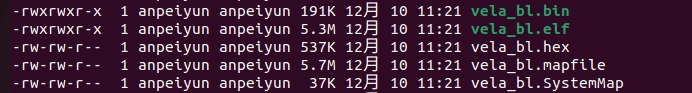
BL Image:./cmake_out/fc7300f8m-evb_kbl
-
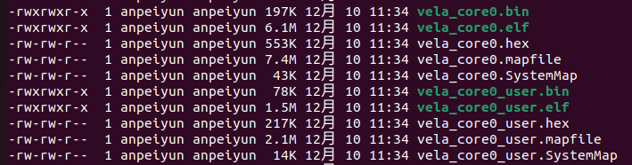
Core0 Image:./cmake_out/fc7300f8m-evb_kcore0
2. Flash Images
You can choose to flash using .hex files (recommended) or .bin files.
Method 1: Flash using .hex files (Recommended)
This method includes address information natively, eliminating the need to manually specify the flash address, making operation safer.
# Flash Bootloader
cd ./cmake_out/fc7300f8m-evb_kbl
echo "loadfile vela_bl.hex" | sudo JLinkExe -if SWD -device FC7300F8MDTxXxxxT1B -speed 4800 -NoGui 1

# Flash Core0 and User images
cd ./cmake_out/fc7300f8m-evb_kcore0
echo "loadfile vela_core0.hex" | sudo JLinkExe -if SWD -device FC7300F8MDTxXxxxT1B -speed 4800 -NoGui 1
echo "loadfile vela_core0_user.hex" | sudo JLinkExe -if SWD -device FC7300F8MDTxXxxxT1B -speed 4800 -NoGui 1
Method 2: Flash using .bin files
Strict specification of the memory start address for each image is required.
# Flash Bootloader (Address: 0x01000000)
cd ./cmake_out/fc7300f8m-evb_kbl
echo "loadfile vela_bl.bin 0x01000000" | sudo JLinkExe -if SWD -device FC7300F8MDTxXxxxT1B -speed 2500 -NoGui 1

# Flash Core0 (Address: 0x01040000) and User images (Address: 0x011C0000)
cd ./cmake_out/fc7300f8m-evb_kcore0
echo "loadfile vela_core0.bin 0x01040000" | sudo JLinkExe -if SWD -device FC7300F8MDTxXxxxT1B -speed 2500 -NoGui 1
echo "loadfile vela_core0_user.bin 0x011C0000" | sudo JLinkExe -if SWD -device FC7300F8MDTxXxxxT1B -speed 2500 -NoGui 1Note: After flashing is complete, you must power cycle (disconnect power and restart) the development board to ensure the system loads correctly.
3. Serial Connection and Verification
Use minicom to connect to the development board's serial port to view startup logs.
-
Execute the following command in the host terminal (assuming the device ID is /dev/ttyUSB0):
sudo minicom -D /dev/ttyUSB0 -b 115200
-
Press the Reset button on the development board.
-
The terminal will output startup information and display the core0> prompt, indicating the system is running normally.

V. Troubleshooting
Q: Ubuntu fails to recognize the serial device /dev/ttyUSB0
Symptom: After connecting the development board, the ttyUSB0 device cannot be found in the /dev/ directory, or the device connection is intermittent.
Cause: The built-in Braille display driver brltty in Ubuntu may occupy the USB-to-Serial device, causing a conflict.
Solution:
sudo apt remove brltty